



Nose-Bridge Through-Hole IR Receiver Module
Nose-Bridge-Shaped Infrared Receiver - Hongcheng Optoelectronics LED Manufacturer
Product Overview:
The nose-bridge-shaped through-hole infrared receiver integrates infrared signal reception, amplification, filtering and demodulation in a small nose-bridge-shaped epoxy resin package. It features small size, high receiving sensitivity, low power consumption, stable output and strong immunity to ambient light interference. Suitable for infrared remote-control systems in home appliances, audiovisual equipment, smart applications, industrial control and security equipment.
Key Advantages:
- Compact bridge-shaped package with a space-saving structure
- Integrated reception, amplification, filtering and demodulation
- High reception sensitivity and stable signal output
- Good resistance to sunlight, lighting and electromagnetic interference
- Three-lead through-hole design for easy installation and soldering
- Carrier-frequency, lead-length and package options available
Applications:
- TVs, set-top boxes and audio/video players
- Air conditioners, fans and smart household appliances
- High-end smart devices and remote-controlled models
- LED luminaires and lighting remote-control systems
- Industrial instruments, automated control and security equipment
- Smart home, communications equipment and consumer electronics products
Product Features:
Photosensitive chip: a high-sensitivity infrared chip provides fast reception response, stable signals and strong interference resistance.
Receiver circuit: integrated amplification, filtering and demodulation circuits provide digital control signals for easy connection to microcontrollers and control circuits.
Package: A compact nose-bridge-shaped epoxy resin package with a clearly defined receiving window provides good insulation and environmental adaptability.
Leads: Three-lead through-hole structure offers good conductivity, with different lead lengths and arrangements available.
Frequency: the common carrier frequency is 38kHz. Other frequencies can be selected according to model and project requirements.
Packaging: Antistatic bags, bulk and specified packaging available for convenient transport, storage and production.
Category: Nose-Bridge Shape
Key Receiver Specifications Quick Reference (by Model)
Ambient temperature 25℃. See the table for each parameter's test conditions and value definitions. “—” means unspecified in the corresponding datasheet. Scroll the table horizontally to view all columns; download the corresponding PDF for complete specifications.
| Part Number | Specifications | Value | Test Conditions / Notes |
|---|---|---|---|
| HC-1738-2.54-2123 | Supply Voltage VCC (Absolute Limit) | 0~7.0 V | PDF absolute maximum rating; not the recommended operating voltage range |
| Carrier Frequency Fin | 37.9 kHz (Typical) | Electrical carrier frequency, not optical wavelength | |
| Horizontal Reception Angle | ±45° | PDF condition: Distance of 5 mm in the horizontal left/right directions | |
| Vertical Reception Angle | ±30° | PDF condition: vertical up/down distance of 5 mm | |
| Operating Current Iop | 180 μA (typical); 300 μA (maximum) | VCC=3 V | |
| Operating Current Iop | 200 μA (typical); 330 μA (maximum) | VCC=5 V | |
| Operating Temperature Top | -20~+80℃ | Operating temperature range under the PDF's absolute limits |


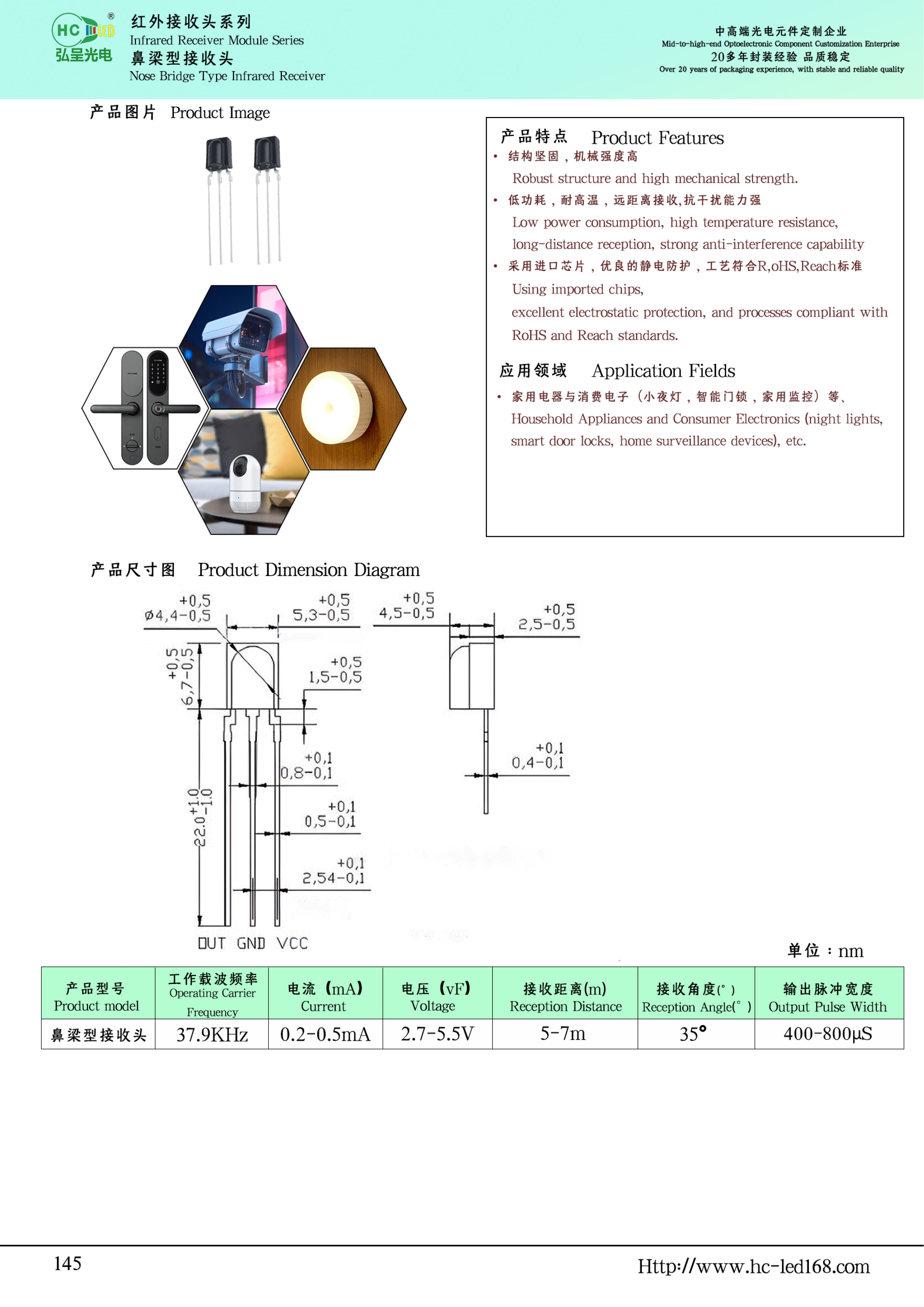
Bridge-Shaped Through-Hole Infrared Receiver Module An infrared receiving device used with a 940nm infrared emitter for remote-control reception and photoelectric sensing. Supplied directly by Dongguan Hongcheng Optoelectronics Co., Ltd. (an international member of Guangyu Group with over 20 years of LED packaging experience), it features Grade A chips and 99.99% pure gold wire bonding, and is RoHS certified. Free samples and customization of carrier frequency, package and leads are available. Download the datasheet PDF on this page for complete electrical specifications and mounting dimensions.
Q: What is the difference between an infrared receiver module and an infrared receiving diode/transistor?
A: The receiver module contains an amplifier/demodulator IC and directly outputs digital signals demodulated from 38kHz, ready for remote-control reception once connected. A photodetector (photodiode) outputs only a weak photocurrent and requires an external amplification/demodulation circuit, mainly for through-beam or reflective sensing.
Product Specifications at a Glance
| Product Name | Bridge-Shaped Through-Hole Infrared Receiver Module |
|---|---|
| Package: | Through-Hole Package |
| Dimensions | Refer to the corresponding datasheet drawing |
| Mounting: | DIP Through-hole |
| Receiving Characteristics | Response wavelength band and sensitivity are subject to the corresponding datasheet and test conditions |
| Environmental Certification | RoHS |
| Manufacturer | Dongguan Hongcheng Optoelectronics Co., Ltd. |
| Customization: | Specify the target model, package and lead requirements; inquire to confirm available specifications |
| Detailed Specifications | See the datasheet PDF on this page for complete electrical parameters |
| Minimum Order Quantity (MOQ) | 1K(1,000 pcs) |
| Sample Lead Time | Typically 3-4 working days |
| Volume Production Lead Time | Typically 10-15 working days |
💡 Typical Applications: Common applications include televisions, set-top boxes and audiovisual players; air conditioners, fans and smart appliances; high-end smart devices and remote-controlled models; LED luminaires and lighting remote-control systems.
Ordering and Inquiry Information
Minimum order quantity: 1K (1,000 pcs); sample lead time is generally 3-4 working days, and volume production lead time is generally 10-15 working days (subject to order confirmation). For volume pricing, use the inquiry form on this page or call/message us on WeChat at 139 2571 4318. Specify the exact model and quantity in your inquiry.
Selection Recommendations
Check supply range, carrier frequency, output logic, reception angle and pin definitions during selection. Follow the selected part number's datasheet for supply decoupling, interface connections and soldering conditions. Do not determine these by emission color or lead length.
Related Reading: LED Indicator Part Number Comparison Table (Complete 2026 Edition) | Datasheet Download Center
Note: The parameters on this page were compiled against product documentation on 2026-09-17. Items not provided in a datasheet are not assigned uniform values. Refer to the datasheet for the relevant part number.
